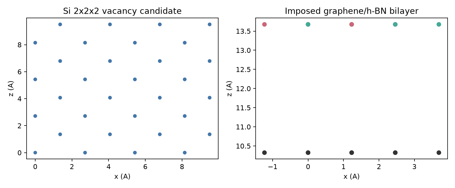
A useful candidate record starts with the scientific alternatives and actual parent objects, not the automation directory. This example keeps two generated constructions deliberately narrow: one unrelaxed Silicon one-site deletion with no encoded charge state, and one graphene/h-BN bilayer whose common in-plane cell is imposed rather than predicted.
Choose the candidate family before deleting or joining atoms
For a defect, identify the accepted pristine parent, symmetry-distinct sites, supercell choices, stoichiometry, possible charge states, and local configurations that must remain separate. Deleting one atom creates a geometry; it does not define a neutral or charged defect calculation.
For an interface, inspect both parents and choose orientation, termination, strain allocation, lateral match, layer order, separation, registry, and vacuum as explicit variables. A common cell or a small scalar mismatch does not identify the stable interface. The related lattice-match and registry guide explains why matching and registry remain separate decisions.
Rebuild the bounded files outside the repository
Run from the repository root. The case copies itself into an empty external directory before generating files, so the committed evidence is not overwritten.
run_root="$(mktemp -d)"
CASE_RUN_ROOT="$run_root" PYTHON=python3 \
  bash examples/cases/structure-defect-interface-candidates/run.sh
bash "$run_root/check.sh"
python3 -m json.tool "$run_root/derived/structure-candidates-report.json"
The Silicon branch writes an eight-atom conventional diamond parent, repeats it to a 64-atom 2×2×2 object, removes the recorded site at fractional coordinate [0, 0, 0], and exports a 63-atom unrelaxed candidate. The interface branch exports eight C atoms and eight alternating B/N atoms in one imposed in-plane cell with an initial separation of 3.35 Å and pbc = [true, true, false].
The reported 0.0% in-plane mismatch is a construction constraint caused by assigning both layers the same in-plane coordinates. It is not a lattice-match prediction, strain assessment, or relaxed epitaxial result.
Inspect the exported parents and children
Read the headers and the structured report before opening a viewer:
sed -n '1,12p' "$run_root/source/si-diamond-conventional.xyz"
sed -n '1,12p' "$run_root/output/si-2x2x2-vacancy.xyz"
sed -n '1,12p' "$run_root/output/graphene-hbn-bilayer.xyz"
ase info --files \
  "$run_root/source/si-diamond-conventional.xyz" \
  "$run_root/output/si-2x2x2-vacancy.xyz" \
  "$run_root/output/graphene-hbn-bilayer.xyz"
Then open the actual files in VESTA, OVITO, XCrySDen, ASE GUI, or another viewer that shows the cell and periodic images. For the vacancy, compare pristine and defective cells, identify the removed site, and inspect remaining coordination and nearest images. For the bilayer, use both top and side views to inspect orientation, registry, layer order, separation, vacuum, and contacts. The stored x-z projection is only a quick geometric reference; it cannot display the vacancy site or lateral registry adequately.
Keep the program check separate from the manual decision
python3 examples/practical-guides/structure_defect_interface_candidates.pyThe companion re-hashes the committed manifest artifacts and checks their recorded atom counts, periodicity, separation, and imposed mismatch. It does not replace inspection of the regenerated files, and it does not construct a new candidate family.
Keep each alternative under a distinct identifier with its parents, transformations, site or registry choice, strain, separation, periodicity, constraints, exported file, and rejection or continuation reason. Before running DFT, choose compatible method and boundary settings and declare the defect-size, interface-size, vacuum, and target-observable convergence tests.
What this example does not establish
The construction and checks establish bounded program-level completion, artifact identity, atom counts, one explicit site deletion, one imposed-common-cell placement, and declared geometry metrics. They do not establish a vacancy formation energy, charge state, concentration, relaxed defect geometry, interface adhesion, stable registry, strain accommodation, band alignment, convergence, or any material-level conclusion. The ASE build documentation and pymatgen core documentation define the software interfaces; they do not validate these candidate geometries.